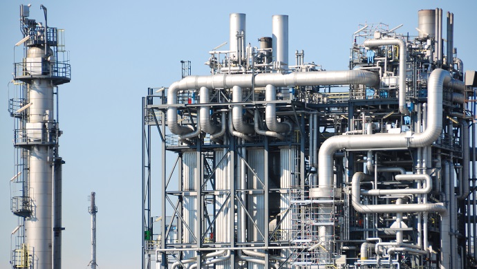
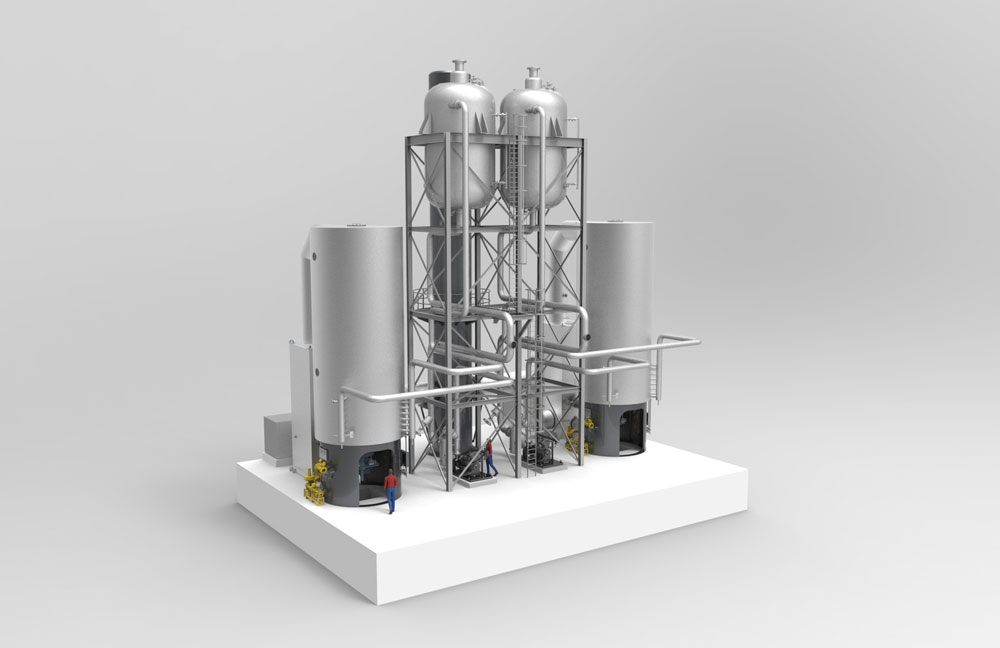
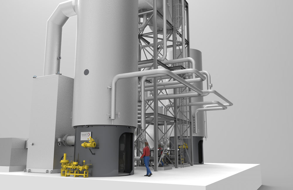
The KAP Diversified Industrial (Pty) Ltd. (HOSAF Division) has reached an agreement with the Bielefeld heat transfer specialist heat 11 GmbH & Co. KG for planning, delivery and commissioning of a diphyl flash heat transfer plant in Durban, South Africa. Aim of HOSAF is to significantly increase the capacity of the PET plant at the Jacobs location (south of Durban). HOSAF (formerly Hoechst South Africa) is the most important PET manufacturer in South Africa.
For the expansion of their production plants up to approx. 600 tons per day of PET, HOSAF will install a new production line. Key element of the plant is the diphyl flash heat transfer plant for the heating of the consumer with 2 x 12 MW of net capacity. The plant is scheduled for delivery still in 2016 the commissioning of the heat transfer plant is planned in the summer of 2017.
In 2001, KAP HOSAF began to produce PET plastics in Durban. In addition to this, HOSAF is running a fiber production plant in Cape Town and a PET recycling plant in Johannesburg.
PET (polyethylene terephthalate) is a thermoplastic polymer in the polyester family produced by polycondensation. PET is used for the manufacture of plastic bottles (PET bottles), films as well as textile fibers.
Conception of the diphyl flash plant
The heating of the consumers is carried out by means of the heat carrier VP-1 (a mixture of diphenyl and diphenyl oxide) on a temperature level of up to 380 °C. The need to use in vapor form makes diphyl the ideal medium for this task. The heat transfer plant was therefore designed as flash plant. The vapor is supplied directly to the consumers. In practice the process heat supply is separated from the diphyl vapor generation. The plant thus is divided into a primary loop which is operated in the liquid phase and therefore operates at a higher pressure level and in a secondary loop with the diphyl vapor generator the so-called flash tank. From here the diphyl vapor flows to the consumer, condensates on the cooler heat transfer surfaces of the individual consumers and flows back into the condensate collecting tank. From there the condensate is fed again into the flash tank respectively directly into the primary loop by means of a condensate pump.
The required pressure reduction for the vapor generation is thereby with a throttle valve immediately at the inlet into the flash tank. Since it is a reduction without change of the enthalpy, a part of the liquid diphyl is vaporized and separated from the liquid phase in the flash tank. The dimensioning of the flash tank is via the specific evaporating surface and the admissible vapor volume flow through the tank.
Design of diphyl vapor plants
The physical laws to be observed at heat carriervapor plants are in principle not basically different to water steam plants. So the heat transfer at the condensation is considerably improved in comparison to the heat transfer at forced convection. However, the heating with condensing vapor requires an elaborate construction of the consumer to enable a free discharge of the condensate. Besides, provisions shall be made in avoiding gas cushions by inert gases on the heat transfer surfaces that can prevent an even heat distribution. This is usually done with constant ventilation at some high positioned places on the individual heat consumers.
Furthermore, all vent pipes of the safety valves are to be submerged in a collection of cold heat carrier to condensate the immediate evaporating heat carrier at the response of the safety valves. This mainly happens in the collection tank on its venting nozzle a water-cooled condenser is attached in addition where necessary. Another plant-specific expense is – depending on climatic local conditions – to be seen with the need to trace heating of all diphyl-carrying pipes to prevent a freezing – the pour point is at +12 °C.
However, much more important is that very large pipe cross sections are required due to the relatively low enthalpy of evaporation of the usually used heat carrier diphyl (just approx. 1/5 of the corresponding value of water steam at the same temperature) and the low density: Referring to the mass flow, the ratio is 1 : 5, referring to the volume flow which is decisive for the dimensioning of the pipe cross sections, the ratio is even 1 : 26.
Burner technology
Chemical processes often accumulate residues that are highly inflammable or have other hazardous properties. To conform to all environmental requirements and regulations and for reasons of cost, the majority of these residues is burned. Essential mark of the installed burner system is the opportunity to use gaseous residues from existing production processes as fuel and to provide a part of the total capacity of 4 MW in resource-saving form. The start-up of the system is realized with natural gas. Furthermore, in case of a temporary failure of the gas supply, a kerosene fuel line can take over the entire heating capacity within a short time and thus ensures the continuing production process. The burner technology for this project is realized with the company ELCO. An air preheater for increasing the firing efficiency to more than 90 % complete this part of the equipment.
High variability
At the engineering of the pump groups and also the gas fitting lines, particular attention was paid to an extensive level of prefabrication at the delivery. The grouping of equipment, piping, fittings and PMC components in form of skids, that means constructive units in frame design, significantly reduces the assembly work at site. This makes a defined introduction of external forces and moments up to the foundations possible. The use of canned motor pumps is a guarantee for long-term high plant availability. The cooling is from the central service water network.
The entire plant is operated according to the industry standard from a control station. The safety data and signals of the heat transfer plant, in particular in the area of the burner and the equipment according to DIN 4754, are processed in a safety-related control. The data transfer to the process control system is via a Profibus connection.
Heat carrier VP1 (diphyl)
The liquid heat carrier VP1 of the manufacturer Eastman is a eutectic mixture of diphenyl and diphenyl oxide. The medium can be used not only in the liquid form but also in the vapor phase at temperatures from +13 ° up to +400 °C. This makes an operation of complex plants at low pressure with ideal temperature distribution at relatively simple system configuration possible.


Comments are closed.